UNIVERSITY OF MARYLAND
UNIVERSITY COLLEGE

Professor Sam Chaudhuri
Foundations of Information Technology
Course MSIT610 Section 9042
UML™ use in the Life Cycle of Systems Engineering
October 22, 2003
Robert D. Betterton
ABSTRACT:
The Unified Modelling Language (UML™) has quickly become the
de-facto standard for building Object-Oriented software and information
systems. It is all about object-oriented modeling. This paper will
show the importance of UML as it applies to the analysis, design and
construction of Information Systems. UML uses a notation that describes software
and informational systems through class diagrams and types, stereotypes, interfaces,
presentation defaults, relationships, and packages. UML was created by the
joint efforts of leading object technologists and represents a convergence of
several object-oriented analysis and design methods including Grady Booch, OMT and
Ivor Jocobson's OOSE. This consolidation of methods has received broadbased industry
support.
Like other notations, UML models object-oriented software or informational
system and is now being applied to systems engineering (by extension), using
several types of diagrams to represent different perspective views of these
systems. Therefore, UML is a progressive language that brings light to any
design of an informational nature. Its use brings board understanding to
systems that all members of a team can easily understand.
Examples of UML constructed systems are Web, XML, stand alone, and vending
machine applications. There are applications in all types of fields.
Finally, UML removes or attempts to remove the ambiguity inherent in systems
design, and of late it is being applied to the discipline of Systems
Engineering.
The Unified Modeling Language is a language for communicating the structure
of systems: an evolutionary, general-purpose, broadly applicable,
tool-supported, and industry-standardized modeling language for specifying,
visualizing, constructing, and documenting the artifacts of a system intensive
process. The UML was conceived to unify the "information systems" and using
the industry's best technology engineering practices as a collection of modeling
techniques. The UML may be applied to different types of systems, software
and non-software domains -- business versus software, and methods or processes.
UML is considered to be the information systems and the world's technology
"universal language."
Because UML is an extensible modeling language, it has created interest
for System Engineers and SE Organizations. One organization INCOSE* is
working very closely with the OMG* in bringing the extended capabilities of
UML to the field of System Engineering.
UML is undergoing explosive growth as the industry standard for data and systems
modeling. It's the cornerstone of many modeling technologies. UML has broad
industry support from the likes of Rational Rose, IBM, and Xerox. UML is one
of the most important developments in systems modeling in the history of
computing. It has been said it is the culmination of many years of systems
modeling/design from the days of structured modeling systems such as DFD, ERD,
Jocoban, modeling systems. Below is a diagram that shows the relationship of
UML as a language in modeling a system (Kleepe, 2003):
Developing a model for an industrial-strength software informational system or
any systems engineering project prior to its construction or renovation is as
essential as having a "blueprint" for a large building. Good models are essential
for communication among project teams and to assure architectural soundness. As
the complexity of systems increase, so does the importance of good modeling
techniques. There are many additional factors of a project's success, but having
a rigorous modeling "language standard" is one essential consideration.
Since the Unified Modeling Language (UML) became the standard notation for software
and systems architecture, it has become the topic of many books, discussions, and
seminars.
INTRODUCTION:
UML has been formally under development since 1994. UML is a distillation
of three major notations and a number of modeling techniques drawn from a
widely diverse methodologies that have been in practice over the previous
two decades. As stated above, UML has become the de facto standard for modeling
object-oriented software/systems for nearly 70 percent of IT shops (Pender, 2003).
After five plus years of real-world application and feedback, UML 2.0 has
just been adopted by the
Object
Management Group (OMG) June 12, 2003.
A LITTLE HISTORY (Origins of UML):
Object-oriented software development techniques have gone through three
stages of evolution:
Object-oriented programming languages were developed and began to be used.
Object-oriented analysis and design techniques were produced to help in
the modelling of businesses, the analysis of requirements and the design of
software systems. The number of these techniques grew rapidly.
During the 1990s many different methodologies, along with their own set
of notations, were introduced to the market. Three of the most popular
methods were OMT (Rumbaugh), Booch, and OOSE (Jacobson). Each method had
its own value and emphasis. OMT was strong in analysis and weaker in the
design area. Booch 1991 was strong in design and weaker in analysis.
Jacobson was strong in behavior analysis and weaker in the other areas.
As time moved on, Booch wrote his second book, which adopted a lot of the
good analysis techniques advocated by Rumbaugh and Jacobson, among others.
Rumbaugh published a series of articles that have become known as OMT-2
that adopted a lot of the good design techniques of Booch. The methods
were beginning to converge but they still had their own unique notations.
The use of different notations brought confusion to the market since one
symbol meant different things to different people. For example, a filled
circle was a multiplicity indicator in OMT and an aggregation symbol in
Booch. You will hear the term "method wars" being used to describe this
period of time. For example, is a class a cloud or a rectangle? Which one
is better? (Quatrani, 2000)
UML was designed to bring together the best features of a number of
analysis and design techniques and notations to produce an industry
standard.
So, what is UML?
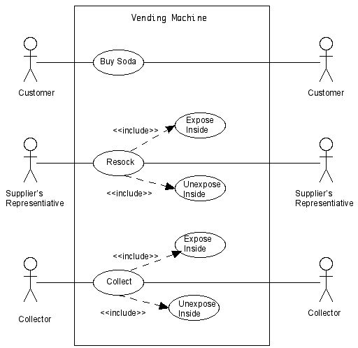
Quite simply, the UML is a visual language for modeling and communicating
about systems (just about any system, see the Use Case vending machine system
below) through the use of diagrams and supporting text. (Schmuller, 2002)
Another example, the diagram below communicates the following (via a Class
Diagram): (Albir, 2003)
- A manager leads a team that executes a project,
- Each manager has a name and phone number, and may initiate a
project or terminate a project.
- Each project has a name, start date, and end date
- Each team has a description, and that is all we are interested in
concerning the team
As stated by the OMG [Object Management
Group] UML is:
The OMG's Unified Modeling Language (UML) helps you specify, visualize,
and document models of software systems, including their structure and
design, in a way that meets all of these requirements. (You can use UML
for business modeling and modeling of other non-software systems too.)
Using any one of the large number of UML-based tools on the market,
you can analyze your future application's requirements and design a
solution that meets them, representing the results using UML's twelve
standard diagram types.
What can you Model with UML? Just about any system you can think of. UML
defines twelve types of diagrams, divided into three categories: Four diagram
types represent static application structure; five represent different aspects
of dynamic behavior; and three represent ways you can organize and manage
your application modules. Below is a list of the modeling diagrams along with
the steps through the UML process.
- Defining Requirements for the Use Case
- Building the Use Case Diagram
- Building the Use Case Narrative
- Identifying the Use Case Scenarios
- The Class Diagram: Associations
- The Class Diagram: Aggregation and Generalization
- Modeling the Static View: The Object Diagram
- Modeling the Functional View: The Activity Diagram
- Modeling the Dynamic View: The Sequence Diagram
- Modeling the Dynamic View: The Collaboration Diagram
- Modeling the Dynamic View: The Statechart Diagram
- Modeling the Extended Features of the Statechart
- Modeling the Development Environment
- Modeling the Static View: The Component Diagram
- Modeling the Static View: The Deployment Diagram
UML IN SYSTEMS ENGINEERING: INCOSE Viewpoint
So why the Model Based Approach, and the expected help from UML.
- Improved communications
- Reduced ambiguity
- Reduced Errors
- More complete representation
- Enhanced knowledge capture
Why use UML for Describing Systems?
- De -- facto standard within the software community
- Robust and extensible language to meet SE needs
- OMG Infrastructure, broad international and industry
representation, and defined adoption process to evolve UML
- Tool vendor and training support
Modeling Language
- UML is a modeling language, and is not a methodology
- Modeling Language = Syntax + Semantics
- Semantics = meaning
- Syntax = representation of meaning
So how does UML help System Engineering?
- Need a system modeling language to address system complexity and
bridge systems & software gap,
- Extending the UML offers a potential solution,
- Established OMG Systems Engineering DSIG with broad participation,
to extend UML from software to systems,
- INCOSE* is leveraging OMG activity to improve the practice of
systems engineering.
Below shows the system requirements for UML use in Systems Engineering:
Below is a diagram of a traditional system software engineering project. But
with a few name changes this process can also be applied to systems
engineering:
The next diagram shows how the traditional systems diagram can be brought
up to date with MDA (Model Driven Architecture) which uses UML extensively.
The above diagram is an alternative notion for the systems engineering
life-cycle. The MDA framework shows PIA (Platform Independent Model) which is
independent of any implemented technology, and PSM (Platform Specific Model)
which is the implementation constructs that are specific implementation
technology. (Kleppe, 2003)
Thus, using the unified modeling language to aid in problem solving on complex
engineering projects is paramount. The areas below show how this can be
done:
- Using static modeling for defining the structure of a system.
- Use behavior modeling for describing interactions within a system.
- With the twelve types of UML diagrams, this will demonstrate how to model
standards and processes, improving the overall communication among the
team members.
- Modeling requirements with use case diagrams, and extending the UML
models with stereotypes, constraints, and tagged values will help
with defining complex systems.
It becomes very apparent to look at UML as an aid to:
- modelling standards,
- processes and procedures,
- requirements engineering,
- implementation of processes,
- assessment of tools,
- defining a quality system,
- an eye towards life-cycles and life-cycle models,
- software and systems,
- maintance
The importance of Requirements elicitation using Use Cases:
Uses Cases specifically addresses the ongoing challenge of managing change
and describes a process for assuring that project scope is successfully
defined and agreed upon by all stakeholders.
Just as the class diagram is a great way to stimulate a client to talk
about a system from their viewpoint, the use case is an excellent tool
for stimulating potential users to talk about a system from their own
ideas and concepts. Its not always easy for users to articulate how
they intend to use a system. Because traditional system development was
often a haphazard process that was short on up-front analysis, users are
sometimes stunned when anyone asks for their input.
The idea is to get system users involved in the early stages of system
analysis and design. this increases the likelihood that the system
ultimately becomes a boon to the individuals it's suppose to help --
instead of a monument to clever cutting-edge computing concepts that
business users find incomprehensible and impossible to work with.
(Schmuller, 2002)
Thus, everyone should be interested in use cases. It is needed if you
wish to deliver a system that satisfies the needs of the customer. The
following roles can benefit from the use case technique of describing
system behavior to get at the needed requirements:
- Customers, who need to be sure that the system that is getting
built is the one that they want.
- Managers, who need to have an overall understanding of what the
system will do in order to effectively plan and monitor the
project.
- Analysts, who need to describe and document what the system is
going to do.
- Developers, who need to understand what the system needs to do in
order to develop it.
- Testers, who need to know what the system is supposed to do so
that they can verify that it does it.
- Technical writers, who need to know what the system is supposed to
so that they can describe it.
- User-experience designers, who need to understand the users' goals
and how they will use the system to achieve these goals.
- And anyone else who wants to better understand what needs to be
built before it is actually constructed.
(Bitter, 2003)
UML TOOlS:
Here is a short list of UML Tools that can be used to craft systems:
Poseidon for UML v1.4, by gentleware.
Mac A&D Developer v7.4.7, by Excel Software.
UML Diagrammer v4.15, by Pacestar.
Rose Professional v2002, by Rational.
Enterprise Architect Professional v3.51, by Sparx Systems.
There are many more.
HOWEVER, UML DOES HAVE SOME CHALLENGIES IN SYSTEMS ENGINEERING:
- UML currently has a shortage of standard notation to address all Systems
Engineering modeling requirements.
- UML has no standard mechanism for requirement analysis, allocation,
and trace- ability.
- UML does not present a standard approach to modeling problem domain
separate from solution domain.
- Need to identify the overlap between system and software domain analysis
and design (to avoid duplicate work). (Steiner, 2002)
But, with the upgrade of UML to version 2 (2003), and the extensions that have
been added, this should help elevate some of these concerns. Bottom line,
UML is a very good tool for just about any type of system modeling bar none.
SUMMARY:
UML is now becoming the required tool of choice in most large companies,
such as Rational Rose, IBM, Xerox, and many others doing object-oriented
software and systems, along with hard real-time systems, such as Web
Applications using Web Services. UML incorporates the best practices
of the best methodologists with the most recent work in the this field. UML
has just been upgraded to v2.0 as of June 12, 2003, by the OMG. This
modeling language has now been around for almost 10 years.
The UML is a standard accedpted by the OMG and has just been adopted by
the ISO group as an abstract UML model in ISO 19115. The ISO Technical
Committee 211 has approved a
project to develop ISO 19139, Geographic information - Metadata -
Implementation specification. ISO 19139 will define a UML implementation
model based upon the abstract UML model in ISO 19115. The UML implementation
model may be used in conjunction with an XML schema, which will be
included in an informative annex to ISO 19139, to describe digital
geographic datasets, (FGDC/ISO, 2003).
UML is used in the Standards Development Organizations and Consortia such
as modeling EDI business processes in
ANSI X12 and Un/CEFACT.
There is also an OMG RFP for using UML in systems engineering, named
"UML™ for Systems Engineering, dated March 28, 2003.
This document is a request for the customization of UML for systems
engineering that is intended to support modeling of a broad range of
systems, which may include hardware, software, data, personnel, procedures,
and facilities (OMG, 2003).
Because UML was created by the joint efforts of leading object
technologists it represents a convergence of several object-oriented analysis
and design methods including Booch, OMT, and Jacobson's OOSE, this makes UML
an ideal modeling tool to:
- Analyze,
- Gather requirements,
- Design,
- Prototype,
- Build,
- Test,
- Deploy, and
- Maintain the systems
UML is being used to effectively construct many mission critical environments
from space exploration to nuclear medicine to automotive systems to web sites.
The UML has sufficient expressive power to capture requirements and analysis
models at a high level of abstraction and still be able to "drill down"
into detailed design concepts such as threads, multitasking, resource
control, and memory management.
References:
- Building Web Applications with UML, 2ed,
Jim Conallen, Addison-Wesley, 2003
- Introduction to the Unified Modeling Language,
Terry Quatrani, Rational Software, 2001
- Learning UML,
Sinan Si Albir, O'Reilly, 2003
- MDA Explained, The Model Driven Architecture: Practice and Promise,
Anneke Kleppe, Jos Warmer, and Wim Bast, Addison-Wesley, 2003
- OMG SEDSIG UML SE Prototype & Evaluation Initial Findings,
Rick Steiner, 2002
- Teach Yourself UML, 2nd Edition
Joseph Schmuller, 2002
- UML Bible,
Tom Pender, Addison-Wesley, 2003
- Use Case Modeling,
Kurt Bittner and Ian Spence, Addison-Wesley, 2003
Organizations:
INCOSE, International Council on
Systems Engineering
OMG, Object Management Group
|
